Allen Bradley Vfd Wiring Diagram

Vt Commodore Ignition Wiring Diagram, Complete Wiring Diagrams For Holden Commodore VT, VX, VY, VZ, VE, VF, 5.36 MB, 03:54, 32,796, John Amahle, 2018-08-01T19:37:41.000000Z, 19, Vt Commodore Ignition Wiring Diagram, to-ja-to-ty-to-my-to-nasz-swiat.blogspot.com, 1272 x 1800, jpeg, bcm pcm 12j swiat nasz, 20, vt-commodore-ignition-wiring-diagram, Anime Arts
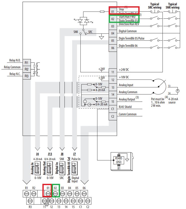
Allen bradley vfd wiring diagram. No patent liability is assumed by rockwell automation, inc. 2 vfds showed in vfd schematic diagram and. A remote temperature (or humidity) sensor is read by the first fan in each zone (fan #1 in zone 1, fan #7 in zone 2, fan #13 in zone 3).
Powerflex 70 wiring diagram. Wiring vfd diagram motor control teco relay external basic abb circuit volt drive fm intended connection questions phase location schematic. These drives offer a motor current up to 720 a, for synchronous or induction motors. Our powerflex 6000 drives meet applications that require variable speed motor control from 2. 2…11 kv, with motor current up to 680 a. Allen bradley micrologix 1100 servo control mr j4 a mitsubishi tutorial plc247 com the basics of reading plc panels and wiring diagrams do supply tech support interfacing rotary encoder to fx5u point programmable logic controller scientific diagram how connect fs24x ab 1771 ide in stock 5 iso input mod 120v ac dc 6 1771i 1000 replacement. Allen bradley powerflex 70 wiring diagram the powerflex drive has an input which can be wired to a fire control panel or other fire/life. This allen bradley 22 a vfd is a 15 horsepower drive. Now that the powerflex 525 vfd is controlled through ethernet/ip, we. Powerflex 753 packaged solutions.
Complete Wiring of Allen Bradley VFD - Free Electrical Software and PLC Trainings

Allen Bradley Vfd Powerflex 753 Wiring Diagram - Wiring Diagram

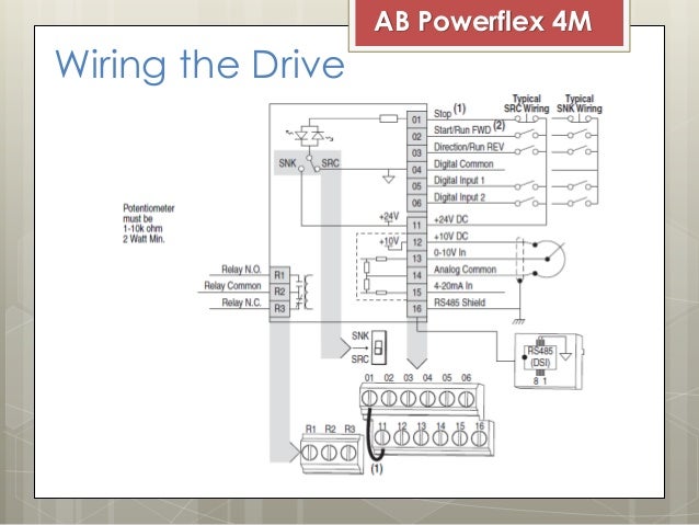
AC Drive VFD - Allen Bradley Powerflex 4M

Wiring Diagram Of Ac Drive

Allen Bradley Vfd Powerflex 753 Wiring Diagram - Wiring Diagram

Allen Bradley Vfd Powerflex 753 Wiring Diagram - Wiring Diagram

Allen bradley vfd powerflex 4m manual
How to do 2 Wires & 3 Wires Source of operation Setting in Allen Bradley VFD - Marine

AC Drive VFD - Allen Bradley Powerflex 4M
Complete Wiring of Allen Bradley VFD - Free Electrical Software and PLC Trainings
