Ac Surge Protector Wiring Diagram
Alternate names of surge protectors are surge suppressors, power strips & transient suppressors. Installation shown in an mnpv12.

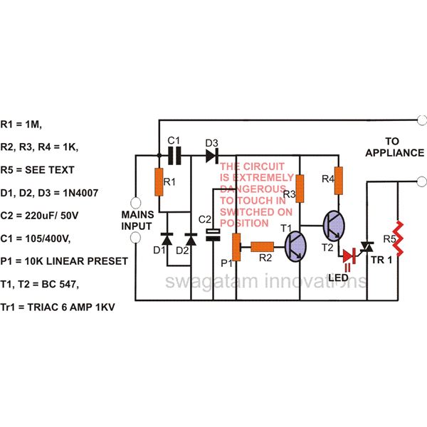
How to Make a Simple AC Mains Surge Protector Device Circuit Diagram Centre
Go back to content table ↑ 1.3 location of surge protection devices.

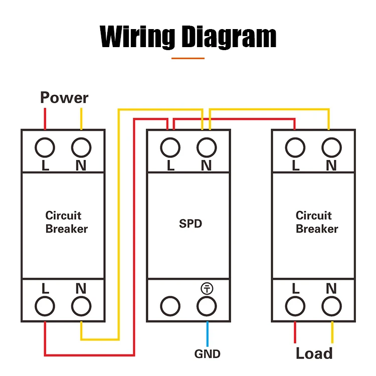
Ac surge protector wiring diagram. (ac) with the power off, connect one wire to ac hot in (line) and other wire to ac hot out (load) as shown in fig. The following represents a wiring diagram of spd’s in a typical system. Whole house surge protector wiring diagram wiring diagram is a simplified pleasing pictorial representation of an electrical circuit.
Page 11 for installation, in addition to the ems kit, you will need: E = (vpeak x i peak) x t2 x k. Together to reduce the impedance of the wire (one twist / inch).
Cheap surge protection doesn’t mean it doesn’t work. Classification and testing of surge protective devices 16 31 requirements in accordance with iec 61643 16 32 important parameters for surge protective devices 17. The circuit diagram of a surge protector is shown below.
A surge protector works by shunting the voltage surge to ground. Vpeak = voltage at peak current. Diesel generator control panel wiring diagram bek3 generator transfer switch electrical wiring diagram.
• always use 10 wire for the hw30c & #6 wire for the hw50c. Making a drawing of the connections to all the component parts in the circuit's load makes it easier to understand how circuit components are connected. 1.2 (dc) connect the red wire to pv + and the black wire to pv.
Type 2 surge protectors are designed to be installed at the service entrance of low voltage systems or close to sensitive equipment to protect against transient overvoltages. Connect the spds neutral wire (white) to the system’s neutral connection. There are a few things to be concerned about, though, so let’s get those out of the way.
It reveals the components of the circuit as simplified shapes, and the power as well as signal connections in between the tools. Installation instructions before transfer box It is also important that the electrical distribution system be grounded and bonded per the national electrical code®.
Surge protector device rating, during normal operation. Note that the first level of surge protection device (1) must be installed as far upstream as possible of the installation in order to reduce as much as possible the induced effects of the lightning by electromagnetic coupling. Β = given for i = ½ x ipeak to ipeak.
Hasil gambar untuk wiring diagram out going panel electrical circuit diagram electrical wiring diagram electrical wiring. Pdf on the selection and installation of surge protection devices in a tt wiring system for equipment and human safety. A circuit diagram or wiring diagram uses symbols to represent parts of a circuit.
K is a constant depending on t2, when t1 is 8 μs to 10 μs. Power surges can cause by defective wiring, faulty devices, and down power lines at the power source that can cause power surges too. The orientation is not critical to the operation.
• in some cases you will need a jumper cable, length to be determined based on the placement of the ems. This installation should be done by a licensed electrician, but i wanted to educate the homeowner about the process of installation and the benefits of a sur. This is a surge protection circuit diagram showing a circuit built with a gas discharge tube.
Two types of spd connections in a tt wiring system download scientific diagram. These devices include two black wires and one white wire. A low value of β corresponds to a low value of vpeak and then to a low value of e.
A wiring diagram is a simplified traditional photographic representation of an electrical circuit. Connect the spds phase a, b, and c wires (black) to the Lightning protection of residential ac wiring k.e.
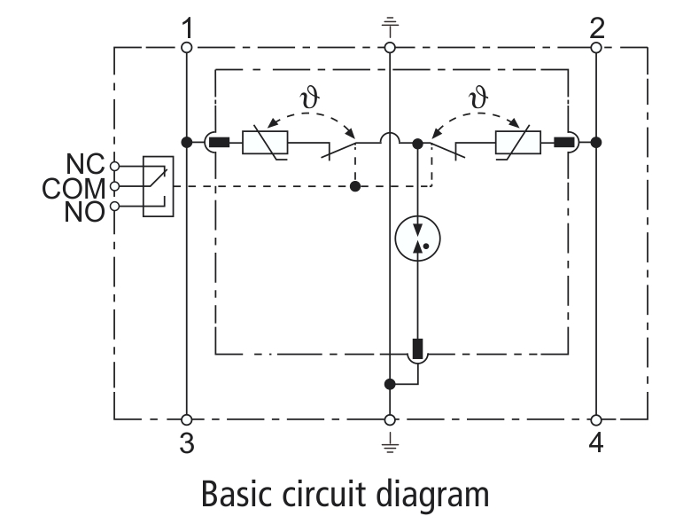
A wiring diagram usually gives suggestion roughly the relative viewpoint and harmony of devices. Scb series connection with spd basic circuit diagram surge protective device spd surge protection. The following represents a wiring diagram of spds in a typical system.
Assortment of surge protector wiring diagram. The national electric code (nec) maximum resistance at ground is 25 ohms. Pv plus bus (red wire) battery negative (black wire) ground ac in (black/red) )wire) ac out (black/red wire) use screw, washer, nut & ring terminal on mnpv combiner.
Home > hvac/r components > surge protection type. 240 volt wiring 120 volt wiring Type 1 surge protectors are heavy duty devices, designed to be installed at the origin of the ac installations equipped with lightning protection system.
Electrical and electronic circuits can be complicated. For effective protection using surge protection devices, it may be. (ac) with the power off, connect one wire to ac hot in (line) and other wire to ac hot out (load) as shown in fig.
Reference this wiring diagram as necessary in steps 2 and 3. China customized surge protector device surge arrester spd surge protection dc 1000v dc 500v dc spd suppliers manufacturers factory wholesale price usfull. First, the unit is not ul certified.
Pay particular attention to fuse or breaker requirements and lead lengths. White wire surge arrestor ground bus black wires scm60 & scm150 wiring diagram: It is very important to follow the manufacturer’s installation instructions.
Drawings for electronic circuits are called circuit diagrams. Surge protection kits 125a power lighting boards hager uk. This is a surge protector.
Locate the electrical system’s applicable wiring diagram in figure 5. The phase wires are black and red in color.
Surge Protection Device,220V surge protection, 110V SPD,230V Surge Protection,three phase SPD


LIGHTING/SURGE PROTECTOR CIRCUIT ElecDude
Surge Diverter Wiring Diagram
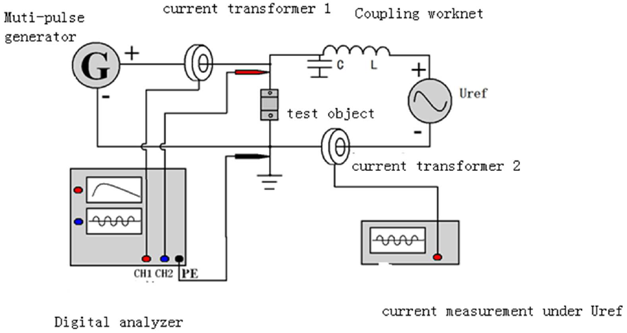
test circuit diagram Surge Protective Device SPD Surge Protection Device

Wiring Diagram For Surge Protector Wiring Diagram Schemas
SURGE PROTECTION CIRCUIT PRINCIPLE AND DESIGN ElectronicsBeliever

Surge Diverter Wiring Diagram

Surge Diverter Wiring Diagram Wiring Diagram And Schematic Diagram Images

How to Make a Simple AC Mains Surge Protector Device Circuit Diagram Centre
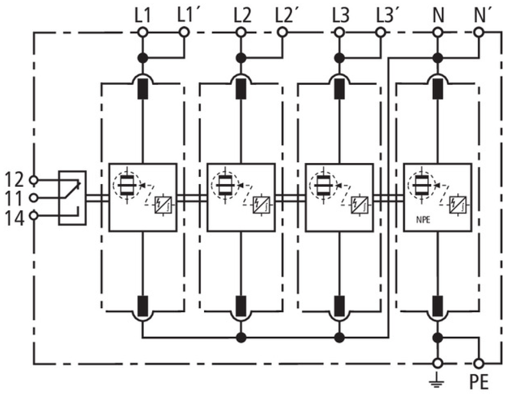
Basic circuit diagram DV M TT 255 FM Surge Protective Device SPD Surge Protection Device
Over Voltage Surge Protection AC 230V

Basic circuit diagram AC surge protector device T1+T2+T3, Iimp 12,5kA DAC113VG31275, part
Surge Protective Device,SPD,AC SPD,220V surge protection, 110V SPD,230V Surge Protection,three


Surge Protection Circuit Wiring View and Schematics Diagram
Surge Protection Circuit

Surge Protective Device Wiring Diagram Complete Wiring Schemas

SURGE PROTECTION CIRCUIT PRINCIPLE and DESIGN ElectronicsBeliever
Basic circuit diagram for AC Surge Protective Device SPD T3, Class D, Class III TLP series
Wiring Diagram For Surge Protector Wiring Diagram Schemas