Wiring And Schematic Diagram
Many wiring diagrams also have a key that provides important information such as wire gauge and colors. A simplified conventional pictorial representation of an electrical circuit.
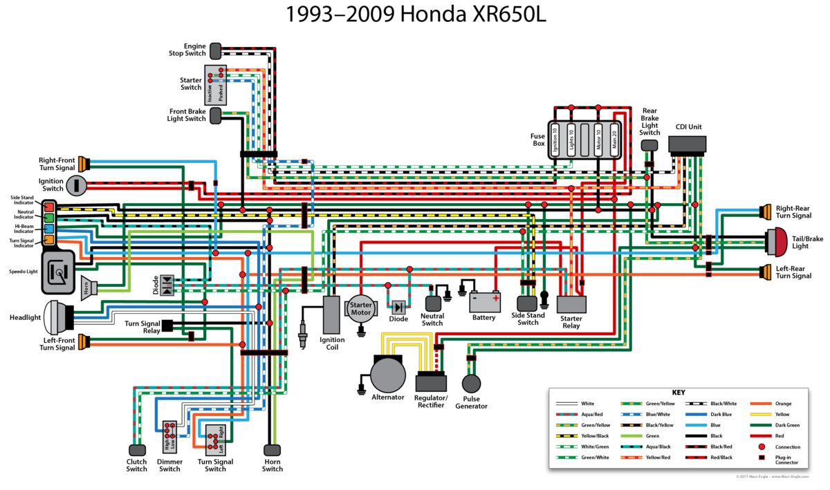
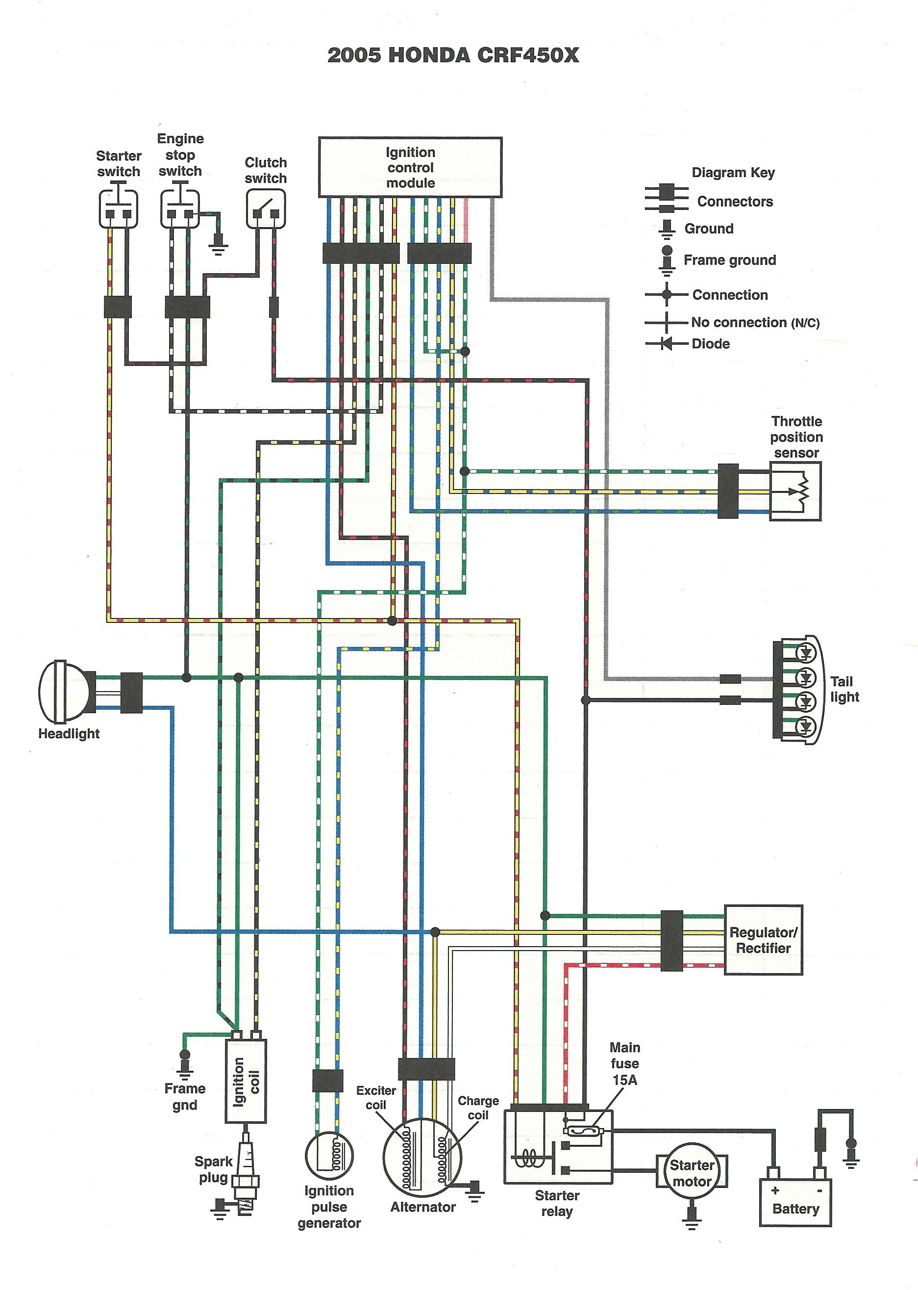
Redrawn Honda XR650L Wiring Diagram Articles ThumperTalk
A wiring diagram usually gives information about the relative position and arrangement of devices and terminals on the devices to help in building or servicing the device.

Wiring and schematic diagram. What is the meaning of schematic diagram sierra circuits. For the fuel/water separator heater wiring schematic, see fig. The table down here will help you better understand the difference between both diagrams.
Basics 8 aov elementary & block diagram : Basics 10 480 v pump schematic : A schematic diagram shows the components and their values and connections in an understandable manner.
Schematics and wiring diagrams circuit 1. A wiring diagram illustrates the physical components of an electric circuit. Create house wiring diagrams, electrical circuit plans, schematics and more smartdraw's wiring diagram software gets you started quickly and finished fast.
Not sure which wires attach to what on your trailer connectors. Basics 13 valve limit switch legend : On the other hand, a schematic diagram depicts the function of the circuit without any concern for the circuit's physical layout.
Wiring diagrams show how the wires are connected and where they should located in the actual device as well as the physical connections between all the components. A schematic diagram is a circuit which shows the connections in a clear and standardized way. A completed wiring diagram can help with the physical installation of wires.
How to read a wiring diagram: A schematic diagram uses symbols to show the elements in a system. A schematic diagram shows the components and their values and connections in an understandable manner.
Electrical drawings and schematics overview. As nouns the difference between schematic and diagram is that schematic is a drawing or sketch showing how a system works at an abstract level while diagram is a plan drawing sketch or outline to show how something works or show the relationships between the parts of a whole. In a schematic circuit diagram, the presentation of electrical components and wiring does not entirely correspond to the physical arrangements in the real device.
In some cases the schematic symbol and the wiring diagram symbol are the same. The schematics it produces look very good. A wiring diagram is sometimes helpful to illustrate how a schematic can be realized in a prototype or production environment.
Basics 14 aov schematic (with block included) basics 15 wiring (or connection. Wiring diagrams show how the wires are connected and where they should located in the actual device, as well as the physical connections between all the components. A schematic circuit diagram represents the electrical system in the form of a picture that shows the main features or relationships but not the details.
Cab wiring schematics for the data link wiring schematic, see fig. Schematic drawing wiring diagrams , also called connection diagrams, however, do show how equipment is laid out and the connections between them. How to read and understand an electrical schematic.
In contrast, the wiring diagram shows how wires are connected to a device and what will be their exact physical location in a circuit. Difference between pictorial and schematic diagrams lucidchart blog. Wiring diagram vs schematic diagram schematic diagrams are electrical layouts that mainly focus on the basic plan and function rather than its physical location.
It shows the components of the circuit as simplified shapes, and how to make the connections between the devices. Also called wiring diagrams or circuit diagrams, these diagrams show how the different components of a circuit are connected. Mechanical schematic diagram symbols pdf wiring diagram line uncategorized wiring diagram line we are make source the schematics, wiring diagrams and technical photos
For the electric horn wiring schematic, see fig. In these diagrams, lines represent connecting wires, while other elements like resistors, lamps, and switches are represented by standardized symbols called electrical schematic symbols. A typical schematic diagram illustrates the location of the components and how they relate to one another.
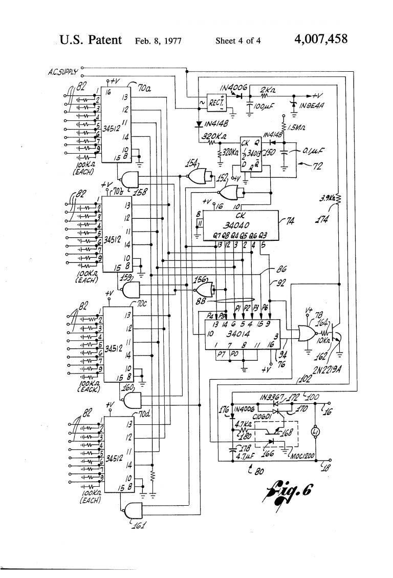
For the fuel level sender wiring schematic, see fig. Figure 4—schematic diagram wiring diagram (or pictorial): They are crucial to the assembly of the circuit or system.
Wiring diagram vs schematic diagram schematic diagrams are electrical layouts that mainly focus on the basic plan and function rather than its physical location. In some cases, the schematic symbol and the wiring diagram symbol are the same. A wiring and schematic drawing.
22 transferring from schematic to wiring diagram for connection purposes. To aid in the development of a wiring diagram, it is useful to start with the circuit’s schematic diagram and the numbering system. A schematic shows the plan and function for an electrical circuit, but is not concerned with the physical layout of the wires.
Wiring diagrams for circuits use the same labels as the schematic. Plus, you can use it wherever you are—smartdraw runs on any device with an internet connection. The arduino should always be disconnected whenever you are wiring.
Wiring diagram is a form of schematic to show the connections which are relevant to the circuit in question. The components of the system are displayed as simple shapes or diagrams. Basics 9 4.16 kv pump schematic :
It is usually used to communicate or intended to convey the connections and working. How is a wiring diagram different from a schematic? A wiring diagram shows the relative layout of the components and the wire connections between them.
Rotork Iq3 Wiring Diagram Honeywell thermostat Schematic

My advice in successful reading singleline, schematic, P
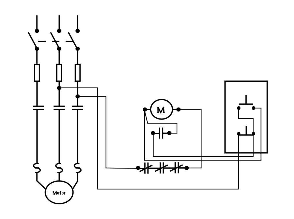
Schematic vs. Wiring Diagrams Basic Motor Control

Toyota Schematic Wiring Wiring Diagrams
What is the difference between schematic diagram and

Ford Wiring Schematics wiring diagram B88 route

electrical wiring diagram examples Wiring Diagram and
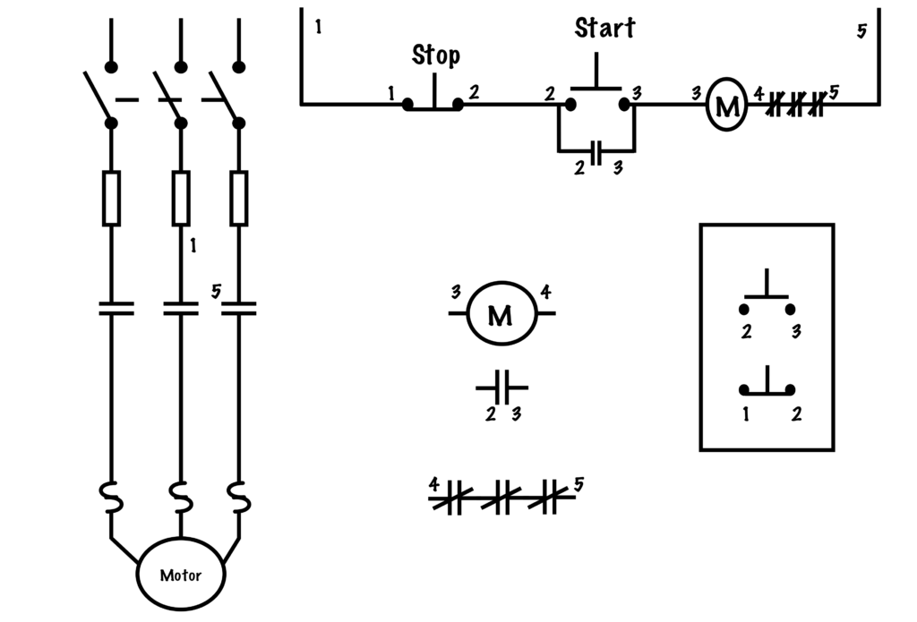
Transferring From Schematic to Wiring Diagram for

What Is A Circuit Diagram Or Electrical Schematics
Dan's Motorcycle "Wiring Diagrams"

What Is The Difference Between Wiring Diagrams And

Turn Signal Wiring Schematic Diagram Database Wiring
Suzuki TC185 wiring diagram Dualsport
Wiring Diagram
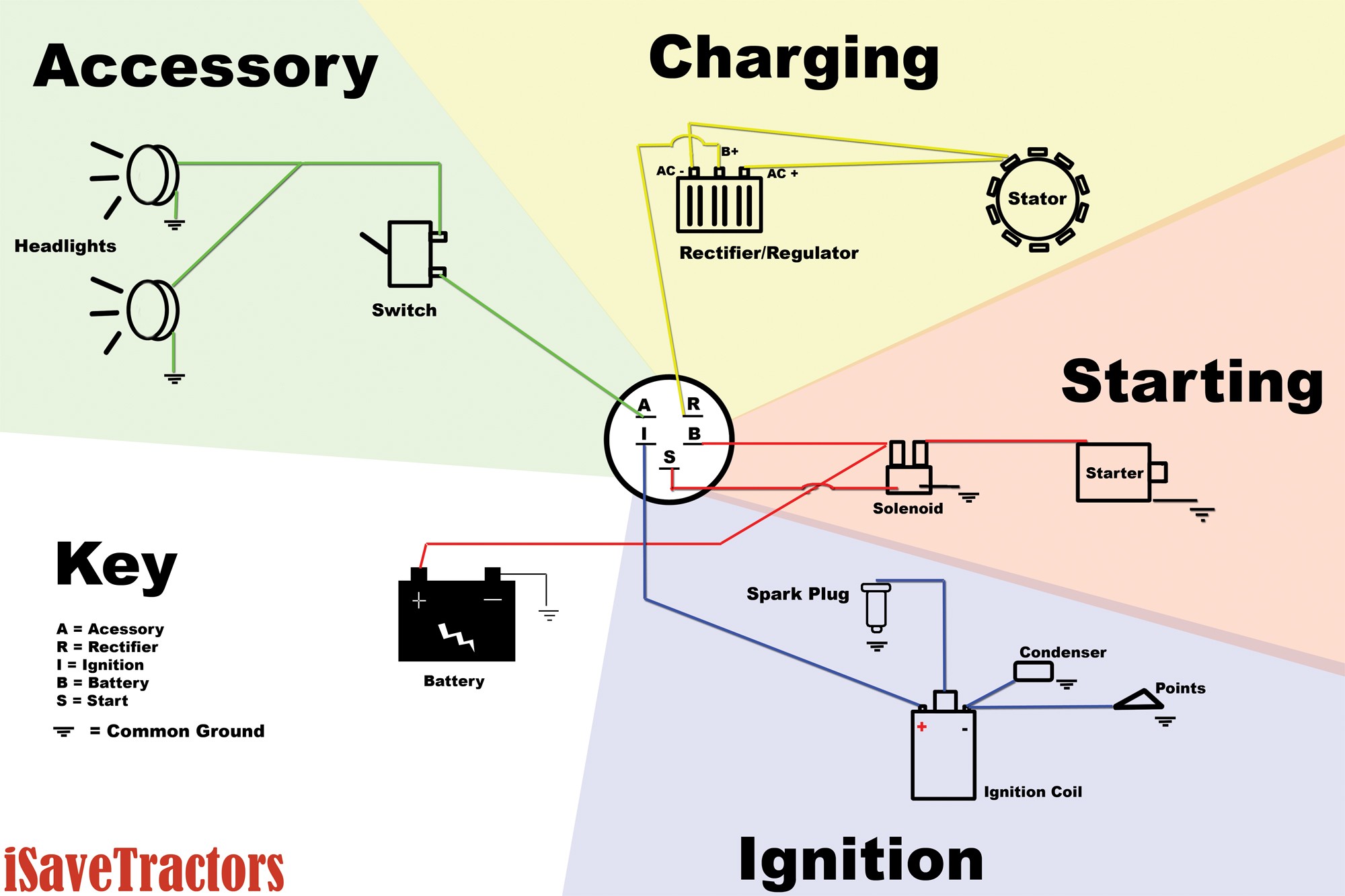
Chevrolet Starting System Wiring Diagram Wiring Forums

Aaon Rooftop Units Wiring Diagram Gallery
Kohler K301 Engine Diagram My Wiring DIagram

Ford Escape Wiring Schematic wiring diagram B88 activity

3 Pole Switch Wiring Diagram autocardesign