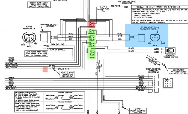
Boss Solenoid Wiring Diagram

Vt Commodore Ignition Wiring Diagram, Complete Wiring Diagrams For Holden Commodore VT, VX, VY, VZ, VE, VF, 5.36 MB, 03:54, 32,796, John Amahle, 2018-08-01T19:37:41.000000Z, 19, Vt Commodore Ignition Wiring Diagram, to-ja-to-ty-to-my-to-nasz-swiat.blogspot.com, 1272 x 1800, jpeg, bcm pcm 12j swiat nasz, 20, vt-commodore-ignition-wiring-diagram, Anime Arts
Control plug pin functions. 13 pin harness 2015+ dodge only. 13 pin harness 2015+ dodge only. The boss snowplow has been carefully designed and built for years of carefree performance.
Refer to the manifold wiring diagram in this manual. Check for voltage between solenoid valve terminal and ground with ignition switch on and control switch in float position. If voltage is present solenoid valve or valve coil has failed. Test power to the control box by checking voltage between black wire and ground at the white. The starter solenoid wiring diagram is no more a mystery. It is very easy. If you don’t know what wires go to the starter solenoid. Here is a quick illustration. Boss v plow solenoid wiring diagram.
GRAFIK Boss Plow Solenoid Diagram Full HD version - TURNTABLEAB.KINGGO.FR

GRAFIK Boss Plow Solenoid Diagram Full HD version - TURNTABLEAB.KINGGO.FR
Boss V Plow Solenoid Wiring Diagram - THE-INSTRUMENT

2002 Polaris Trail Boss 325 Wiring Diagram Solenoid
Bos Plow Solenoid Wiring | Wiring Diagram Database

37 Boss Snow Plow Solenoid Wiring Diagram - Wiring Diagram Online Source

Boss Snow Plow Solenoid Diagram | Car Wiring Diagram

Boss V Plow Solenoid Wiring Diagram - easywiring
