Ceiling Fan Wiring Diagram With Capacitor Connection

Vt Commodore Ignition Wiring Diagram, Complete Wiring Diagrams For Holden Commodore VT, VX, VY, VZ, VE, VF, 5.36 MB, 03:54, 32,796, John Amahle, 2018-08-01T19:37:41.000000Z, 19, Vt Commodore Ignition Wiring Diagram, to-ja-to-ty-to-my-to-nasz-swiat.blogspot.com, 1272 x 1800, jpeg, bcm pcm 12j swiat nasz, 20, vt-commodore-ignition-wiring-diagram, Anime Arts
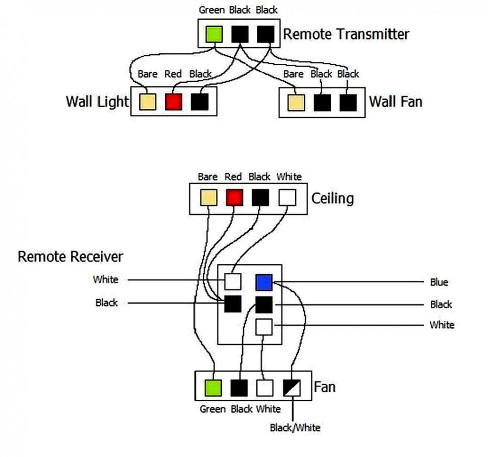
Ceiling fan connection with capacitor diagram ceiling fan consists of two windings inside motor namely starting winding and running winding. Here starting winding also called as auxiliary winding and running winding also called as main winding. Usually, we use a 2. 5/3. 5 microfarad capacitor in the ceiling fan. In order to wire a device by observing a diagram, you have to know the function of the components also.
For more clear realization i will show the winding connection circuit separately. Ceiling fan regulator circuit ceiling fan capacitor connection you ceiling fan installation primary and secondary winding ke how to connect my old table fan motor directly power plug it connection of fan circuit diagram with capacitor part 3. In this video i will show you ceiling fan connection, ceiling fan starting running winding wire connection, how to identify ceiling fan running and starting. Wiring capacitor 20diagram 20wiring capacitors. Wiring capacitors in series. What is the use of capacitor in fan. Cbb61 wiring diagram to 3 speed switch Effectively read a wiring diagram, one offers to learn how typically the components within the program operate. For example , in case a module will be powered up and it sends out the signal of fifty percent the voltage and the technician would not know this, he would think he offers a problem, as he or she would expect a 12v signal.
[Proper] Ceiling Fan Connection with Regulator, Switch and Capacitor - ETechnoG | Electronic
![Ceiling Fan Wiring Diagram With Capacitor Connection [Proper] Ceiling Fan Connection with Regulator, Switch and Capacitor - ETechnoG | Electronic](https://i.pinimg.com/originals/f3/e4/99/f3e4990331373f2daacd86d382434a1a.png)
Hunter Ceiling Fan 3 Speed Capacitor Wiring Diagram
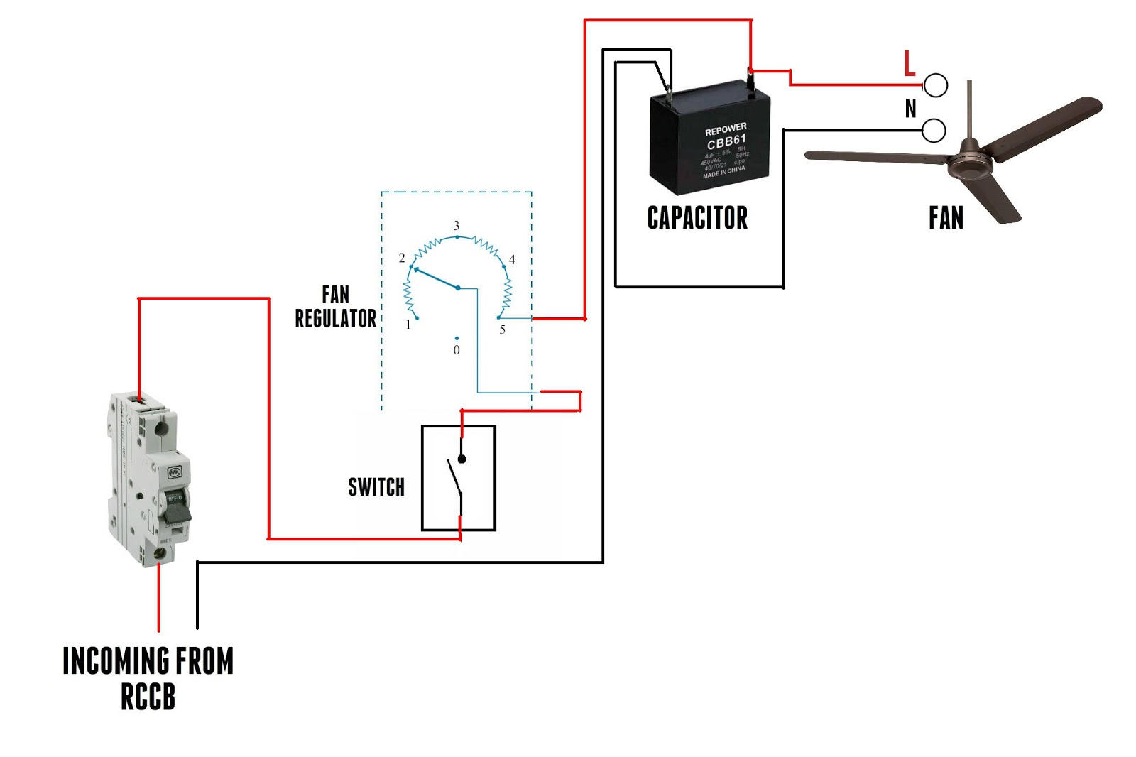
Ceiling Fan 3 Wire Capacitor Wiring Diagram - Electricalonline4u

5 Wire Ceiling Fan Capacitor Wiring Diagram - Cadician's Blog
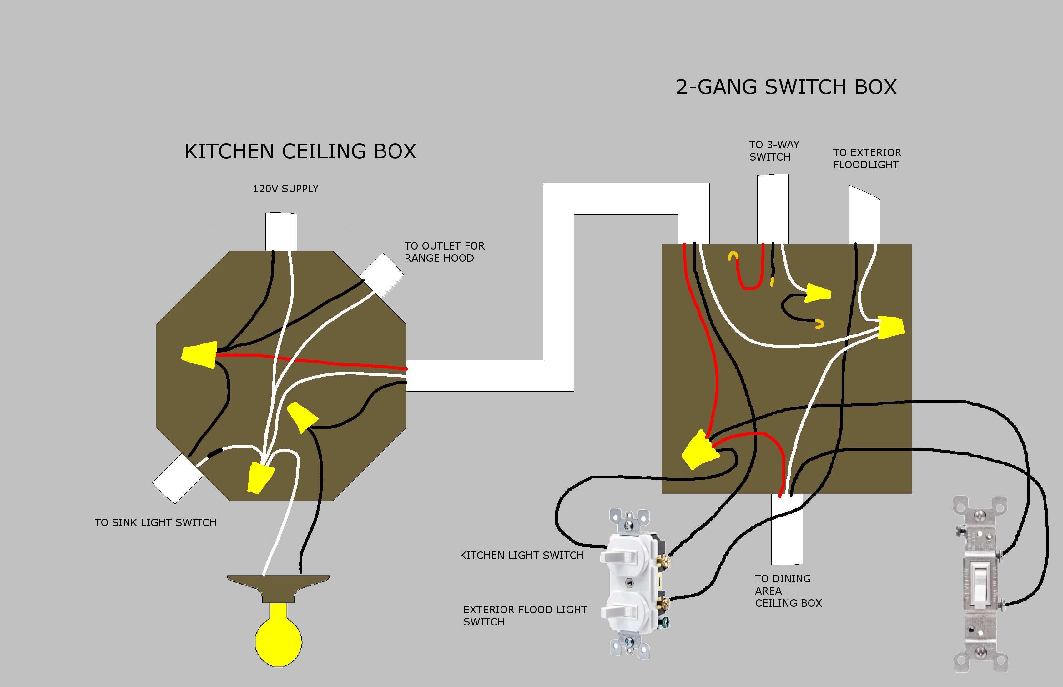
Get Hampton Bay Ceiling Fan Capacitor Wiring Diagram Download

8 Images Installing 5 Wire Ceiling Fan Capacitor And Description - Alqu Blog
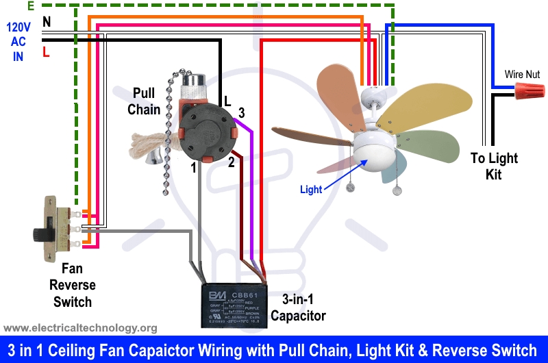
Hunter Ceiling Fan Switch Wiring Diagram | Wiring Diagram
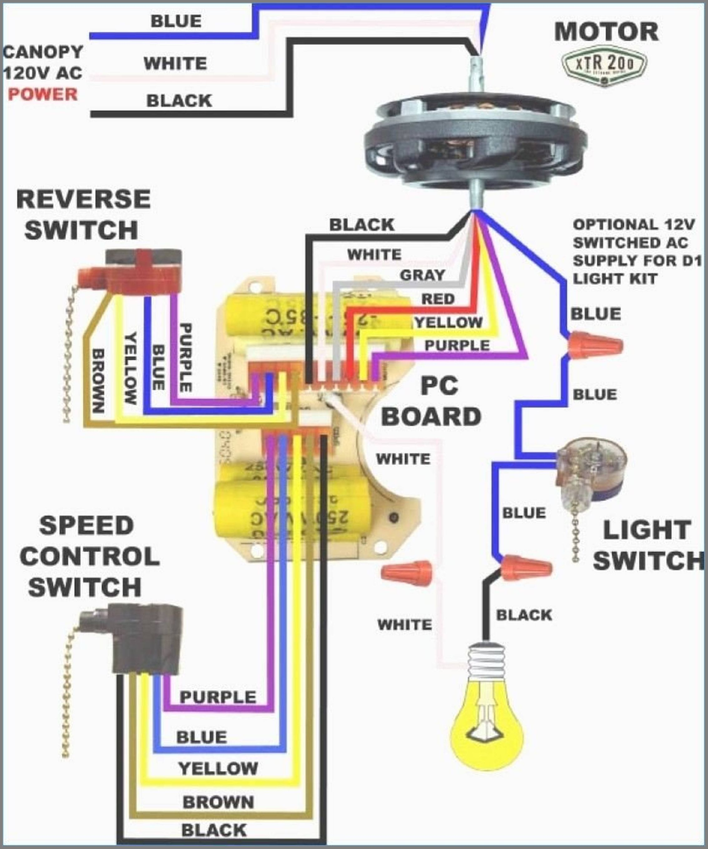
Ceiling Fan Capacitor Wiring Diagram | Cadician's Blog
8 Photos Winding Connection Of Ceiling Fan And Description - Alqu Blog

Hunter Ceiling Fan 3 Speed Capacitor Wiring Diagram
